Contact Us Now

O-Ring Engineering Tools for Industrial Sealing Design
Professional engineering resources including O-Ring size charts, hardness references, and groove design tools for industrial sealing systems.
Industrial O-Rings require accurate dimensional selection, correct elastomer compatibility, and optimized groove design to ensure long-term sealing performance. This Engineering Tools hub provides structured technical resources supporting AS568, ISO 3601, and DIN 3771 standards.
These tools assist engineers in size verification, gland calculation, hardness selection, and compression ratio validation for critical sealing applications.
O-Ring Size Charts
Standard AS568 and metric O-Ring dimensions including ID, cross section, and tolerances.
Hardness Chart
Reference Shore A hardness ranges and application recommendations for industrial elastomers.
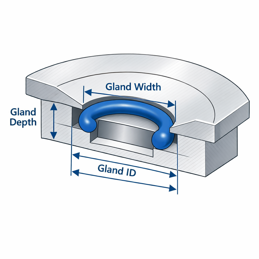
Groove Calculator
Calculate squeeze, stretch, gland fill, and compression ratio for static and dynamic seals.
Design Guide
Engineering guide covering surface finish, extrusion limits, and clearance gaps.
Why Engineering Tools Matter in Sealing Design
Incorrect O-Ring sizing and groove design remain leading causes of sealing failure. Common failure risks include over-compression damage, under-compression leakage, extrusion under pressure spikes, and premature compression set.
Engineering validation reduces development risk and improves system reliability for OEM manufacturers and R&D engineers.
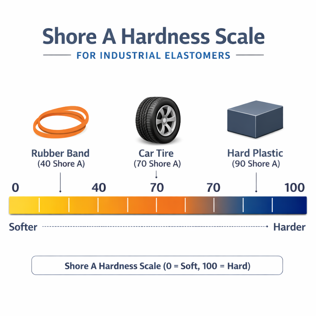
Understanding O-Ring Hardness & Material Reference
Material hardness significantly impacts sealing force and extrusion resistance. Selecting the correct durometer (Shore A) is critical for optimizing sealing performance in both static and dynamic environments.
- 60 Shore A: Softest, ideal for low-pressure vacuum or gas sealing.
- 70 Shore A: Industry standard for most general hydraulic and pneumatic applications.
- 90 Shore A: High hardness for high-pressure systems to prevent extrusion.
Industry Applications & Use Cases
Hydraulic & Pneumatic Systems
Cylinder seals, valve bodies, piston and rod applications requiring high-pressure resistance.
Automotive Manufacturing
Fuel systems, engine sealing, and transmission components with thermal cycling requirements.
Oil & Gas Exploration
High-pressure wellhead and downhole sealing systems exposed to aggressive media.
Industrial Machinery
Gearboxes, pumps, compressors, and heavy equipment sealing systems.
Standards Referenced in Engineering Tools
- AS568: Aerospace Standard for O-Ring dimensions (Inch)
- ISO 3601: Fluid power systems — O-rings
- DIN 3771: Fluid systems; O-rings; dimensions, tolerances
- ASTM D2000: Standard Classification System for Rubber Products
- REACH / RoHS: Environmental regulatory compliance
Frequently Asked Questions
What is the most important factor in O-Ring selection?
Correct size and material compatibility are the primary factors. Even high-quality elastomers will fail if compression ratio, gland dimensions, or fluid compatibility are incorrect.
How do I choose between AS568 and metric O-Rings?
AS568 is commonly used in North America and inch-based systems. ISO 3601 and DIN 3771 are preferred for metric-based global projects. Selection depends on equipment design origin.
What compression percentage is recommended for static seals?
Typically 20–30% compression is recommended for static applications. Exact values depend on material hardness and temperature range.
When should a backup ring be used?
Backup rings are recommended in high-pressure systems to prevent extrusion, particularly when clearance gaps are large or pressures exceed 10 MPa.
Ready to Optimize Your Sealing Performance?
Our engineering team supports OEM, EPC, and industrial equipment manufacturers worldwide with custom sealing solutions.